

Security policy

Delivery policy

Return policy
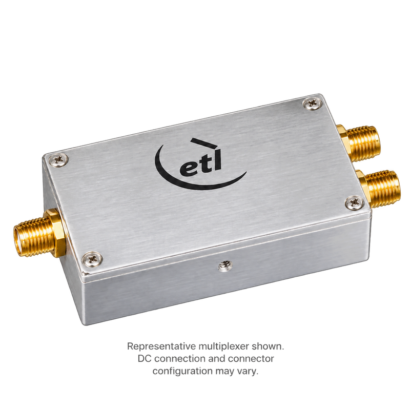
ETL Systems MUXL1P-4113 L-Band & 10 MHz Multiplexer with DC Injection 850–2150 MHz
The ETL Systems MUXL1P-4113 combines or separates L-band RF and an externally supplied 10 MHz reference. A separate DC injection connection supports an external DC feed for indoor satellite communications and RF distribution systems.
The diagram supplied in the datasheet shows a common port carrying L-band RF, 10 MHz, and injected DC. It shows the separate L-band port blocking DC and rejecting 10 MHz, while the reference port passes 10 MHz and blocks RF and DC. The injection connection is marked 8–48 V.
Mean L-band insertion loss is listed as no more than 0.4 dB for the first three connector columns and 0.6 dB for the final column. The clearly identified 50Ω SMA and N-type versions provide L-band flatness of ±0.35 dB.
The compact enclosure supports tapped screw and through-hole mounting. Maximum RF input power is +21 dBm (125 mW), with a maximum DC voltage rating of 50 V on any RF port.
Specifications
Model: MUXL1P-4113
Product Type: L-band and 10 MHz multiplexer / diplexer with external DC injection
Frequency Range: 850–2150 MHz L-band path
Reference Frequency: 10 MHz
Common Port Routing: RF, 10 MHz, and DC pass, as shown in the supplied diagram; confirm before ordering
Separate L-Band Port: RF pass, DC block, and 10 MHz rejection, as shown in the supplied diagram
Reference Port: 10 MHz pass; RF and DC blocked, as shown in the supplied diagram
DC Injection: Diagram marked 8–48 V; confirm permitted range and current capacity
Confirmed Connector Options: 50Ω SMA or 50Ω N-type; other listed configurations require clarification
Mean L-Band Insertion Loss: ≤0.4 dB for SMA/N-type versions
L-Band Flatness: ±0.35 dB for SMA/N-type versions
Typical 10 MHz Insertion Loss: 0.3 dB for SMA; 0.4 dB for N-type
Maximum Operating Limits: +21 dBm (125 mW) RF input; 50 V DC on any RF port
Housing Dimensions: 76.10 × 50.40 × 18.80 mm, excluding connector and DC connection projections
Operating / Storage Temperature: 0°C to +45°C / −20°C to +75°C
Environment: Indoor use; 85% maximum non-condensing humidity; 10,000 ft maximum altitude
Connector Configurations
• MUXL1P-4113-S5S5S5: 50Ω SMA
• MUXL1P-4113-N5N5N5: 50Ω N-type
• MUXL1P-4113-B5B5B5: Listed as 75Ω BNC in the datasheet; confirm impedance and ordering code
• MUXL1P-4113-B7B7B7: Listed as 75Ω F-type in the datasheet; confirm connector type and ordering code
The manufacturer’s V2.1 datasheet contains conflicting connector descriptions. Its 10 MHz loss table also labels a higher loss row “Minimum,” and two typical values appear as “05.” Confirm the affected specifications before selecting these configurations.
Key Features
• L-band coverage from 850–2150 MHz.
• Combines or separates an externally supplied 10 MHz reference.
• Separate connection for external DC injection.
• Low RF insertion loss.
• Clearly identified 50Ω SMA and N-type configurations.
• Compact, rugged enclosure.
• Tapped screw and through-hole mounting options.
This listing covers one MUXL1P-4113 multiplexer in the confirmed connector configuration. External DC supplies, reference sources, RF equipment, cables, and mounting accessories are sold separately unless included in the quoted configuration. The unit does not generate DC power or a 10 MHz reference. The supplied routing diagram is labeled MUXL1P-4103; confirm its applicability, DC injection range, current capacity, polarity, and connector configuration when requesting a quotation. RF input must remain within +21 dBm (125 mW).
