

Security policy

Delivery policy

Return policy
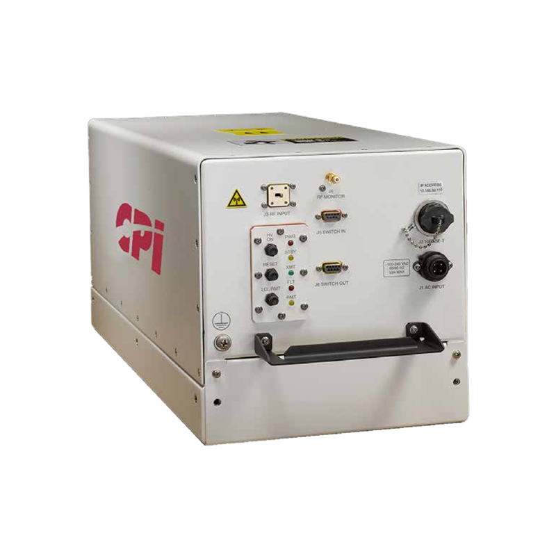
CPI TL07KO-A1 750 W Peak Ka-Band Outdoor TWTA
The CPI TL07KO-A1 is a compact, weatherproof 750 W peak Ka-band outdoor traveling wave tube amplifier for wideband single- and multicarrier satellite uplinks. It supports up to 4 GHz of instantaneous bandwidth within 27.0–31.0 GHz and delivers 625 W peak, 325 W CW and up to 325 W linear output power at the flange.
Output Frequency Range: Customer-selected range within 27.0–31.0 GHz
Instantaneous Bandwidth: Up to 4,000 MHz
Multi-Band BUC Option: Two factory-set frequency ranges, each up to 1 GHz
TWT Peak/CW Power: 750/450 W (58.75/56.5 dBm)
Flange Peak/CW Power: 625/325 W (57.95/55.1 dBm)
Linear Output Power: Up to 325 W at the flange
Gain: 70 dB min. at rated output; 70 dB typ. at small signal
RF Level Adjustment Range: 0–30 dB typ. via PIN-diode attenuator, in 0.1 dB steps
Gain Stability: ±0.25 dB max. over 24 hours at constant drive and temperature after 30-minute warmup
Gain Stability Over ±10°C: ±0.75 dB max.
Gain Stability Over Operating Temperature: ±1.0 dB typ.
Small-Signal Gain Slope: ±0.04 dB/MHz max.
Gain Variation Over Any 500 MHz: 1.2 dB peak-to-peak max.
Gain Variation Over Any 1 GHz: 2.5 dB peak-to-peak max.
Input/Output VSWR: 1.3:1 max.
Load VSWR: 1.5:1 max. for full specification compliance; 2.0:1 max. for continuous operation; operation without damage at any value
Phase Noise: 15 dB below the IESS-308 continuous mask; 3 dB below with optional BUC
AC Fundamental Spurious: -47 dBc
Sum of Spurious Signals: -50 dBc
Spurious Output: -60 dBc max.
AM/PM Conversion: 2.0°/dB max. at up to 4 dB output backoff
Harmonic Output: -12 dBc max. at rated power; -60 dBc with optional harmonic filter
Noise Density Below 21.2 GHz: Less than -150 dBW/4 kHz
Passband Noise Density: Less than -70 dBW/4 kHz max.; less than -80 dBW/4 kHz typ.
Intermodulation Relative to Carrier Sum: -28 dBc at 53.95 dBm total output power
Intermodulation Relative to Each Carrier: -25 dBc at 53.95 dBm total output for two equal carriers spaced 5 MHz apart
Noise Power Ratio: -19 dB at 53.95 dBm flange output power
Group Delay Over 40 MHz: 0.01 ns/MHz linear max.; 0.001 ns/MHz² parabolic max.; 0.5 ns peak-to-peak ripple max.
Amplitude and Phase Linearity: Exceeds MIL-STD-188-164A
Primary Power: Single-phase 120–240 VAC ±10%, 47–63 Hz
Power Consumption: 1,300 VA typ.; 1,700 VA max.
Power Factor: 0.95 min.; 0.99 typ.
Cooling: Forced air with integral blower
Operating Temperature: -40°C to +55°C in direct sunlight; up to +60°C out of direct sunlight
Non-Operating Temperature: -54°C to +71°C
Relative Humidity: 100% condensing
Operating Altitude: Up to 10,000 ft. with standard derating of 2°C per 1,000 ft.
Non-Operating Altitude: Up to 50,000 ft.
Shock: 20 g peak, 11 ms half-sine pulse
Vibration: 2.1 g RMS from 5–500 Hz, non-operating
RF Input: WR-28F; WR-34F optional
RF Output: WR-34G; WR-28G optional
RF Output Monitor: 2.9 mm SMA female
Standard M&C Interface: Ethernet with integral web server
Optional Serial Interface: RS-422/485
Dimensions: 10.25 × 10.50 × 22.25 in. (261 × 267 × 566 mm)
Weight: 65 lb. (29.48 kg) without options
Heat Dissipation: 1,400 W max.
Acoustic Noise: 68 dBA nominal at 3 ft.
Compliance: CE marked; ISO 9001:2015 quality management
Key Features:
• 750 W peak and 450 W CW Ka-band TWT power
• 625 W peak and 325 W CW output power at the flange
• Up to 325 W linear output power
• Customer-selected frequency coverage within 27.0–31.0 GHz
• Up to 4 GHz instantaneous bandwidth
• Wideband single- and multicarrier satellite operation
• Compact, rugged and weatherproof outdoor enclosure
• Ideal for fixed earth station applications
• High-efficiency helix traveling wave tube
• 70 dB minimum gain at rated output
• PIN-diode attenuation in 0.1 dB steps
• Integrated Ethernet interface and web server
• SNMP v1, v2 and v3 support
• CAN-Bus architecture for improved reliability and noise immunity
• Built-in fault diagnostics and remote monitoring
• Optional single- or multiband L-band block upconverter
• Optional internal switch control and drive
• Optional redundant or power-combined systems
• Optional uplink power control
• Optional harmonic filter for -60 dBc harmonic output
• Optional liquid-cooled configuration
• Optional RS-422/485 serial interface
• Optional remote control panel
• Optional TWT LifeExtender/LifePredictor technology