
Discontinued – Contact Us for Availability or Replacement

Security policy

Delivery policy

Return policy
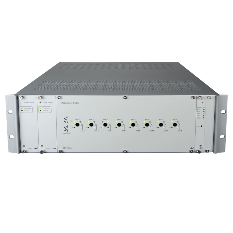
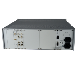
DEV 1993 L-Band Antenna Redundancy Switch, m×n+1
The DEV 1993 L-Band Redundancy Switch provides automatic RF-path redundancy for satellite antenna systems. Its configurable m×n+1 architecture allows one, two or four related signal paths to be switched in parallel between a standby antenna and groups of four to 16 main antennas.
Integrated RF sensing automatically transfers affected signal paths when the monitored level falls below an adjustable threshold. The system supports LNB power with current monitoring, Ethernet and RS-232 control, redundant power supplies, signal recording, data backup, SNMP and the DEV Web Interface.
Optional motorized-antenna control supports automatic antenna positioning in redundancy systems. Dual-band redundancy is also available for motorized antennas equipped with C-band and Ku-band feed systems.
Product Type: Automatic L-band antenna redundancy switch
Redundancy Architecture: m×n+1
Parallel Redundancy Units (m): 1, 2 or 4
Main Channels per Unit (n): 4, 6, 8, 10, 12, 14 or 16
50 Ohm Frequency Range: DC and 700-2450 MHz
75 Ohm Frequency Range: DC and 700-2300 MHz
50 Ohm Connectors: SMA female
75 Ohm Connectors: Precision F female
Main-Input Return Loss: Greater than 14 dB
Main-Output Return Loss: Greater than 18 dB
Redundancy-Path Return Loss: Greater than 12 dB
Input-Port Isolation: Greater than 60 dB
Group-Delay Distortion: Less than 7 ns
Relay Type: Latching
Maximum Switching Power: Less than 30 dBm
Switching Life: Greater than 10 million cycles
RF-Sensing Threshold: Adjustable from -50 to 0 dBm
Threshold Accuracy: ±3 dB
Threshold Repeatability: Less than 0.5 dB
LNB Power: 15 VDC, up to 500 mA per redundancy module
LNB Current Monitoring: Adjustable upper and lower alarm thresholds
Remote Interfaces: Ethernet and RS-232
Remote Management: DEV Web Interface and SNMP
Power Supply: Redundant 100-240 VAC inputs
Power Consumption: Less than 100-200 VA, configuration-dependent
Chassis Height: 3, 6 or 9 RU, configuration-dependent
Dimensions: 483 mm W x 495 mm D
Weight: Typ. 8-25 kg, configuration-dependent
Environmental Conditions: ETS 300019 Part 1-3 Class 3.1E
Available Models
• DEV 1993/50/m×n+1: 50 Ohm redundancy switch with SMA female connectors
• DEV 1993/75/m×n+1: 75 Ohm redundancy switch with precision F female connectors
• Specify m as one, two or four parallel redundancy units
• Specify n as 4, 6, 8, 10, 12, 14 or 16 main channels per redundancy unit
Available Options
• Motorized Antenna Control: Provides web-based manual or automatic positioning for two- and three-axis antennas
• Automatic Antenna Redundancy: Available for configurations with two or four parallel redundancy units
• Dual-Band Redundancy: Supports motorized antennas with C-band and Ku-band feed systems
• Additional 50 Ohm Redundancy: Adds a secondary 2×s+1 system with SMA connectors
• Additional 75 Ohm Redundancy: Adds a secondary 2×s+1 system with F connectors
• Antenna-Controller Interface: Adds a serial interface for compatible antenna controllers
Key Features
• Configurable m×n+1 antenna redundancy architecture
• One, two or four signal paths switched in parallel
• Four to 16 main channels per redundancy unit
• Automatic switching through integrated RF sensing
• Adjustable RF detection threshold
• 50 Ohm and 75 Ohm configurations
• Greater than 60 dB input-port isolation
• Latching relay technology
• Integrated LNB power and current monitoring
• Optional two- or three-axis motorized-antenna control
• Optional automatic antenna positioning
• Optional C-band and Ku-band dual-band redundancy
• DEV Web Interface
• Ethernet and RS-232 control
• SNMP monitoring and control
• Signal recording and data backup
• Redundant AC power supplies

Discontinued – Contact Us for Availability or Replacement