

Security policy

Delivery policy

Return policy
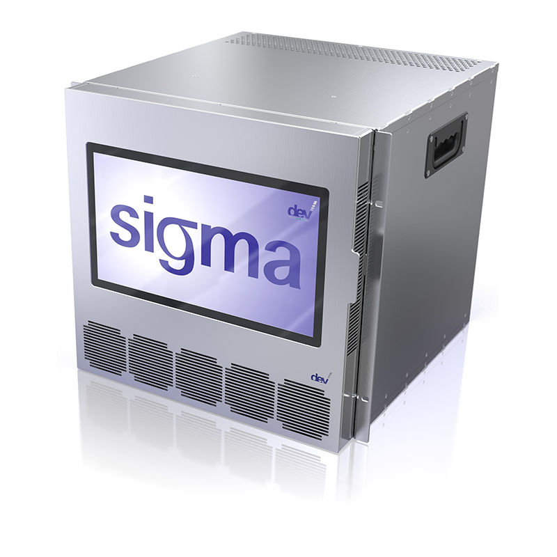
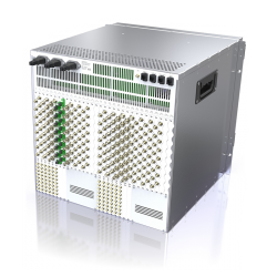
DEV 19128 SIGMA ARCHIMEDES L-Band Matrix Switch, up to 128x128
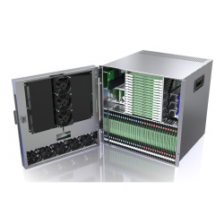
The DEV 19128 SIGMA ARCHIMEDES L-Band Matrix Switch provides scalable routing for up to 128 inputs and 128 outputs within a compact 19-inch, 10 RU chassis. Designed for teleports, satellite ground stations, broadcasters and mission-critical RF networks, SIGMA combines high-density signal routing with modular expansion, hot-swappable components and advanced redundancy.
Input and output capacity can be configured in increments of eight channels and upgraded in the field. Multiple DEV 19128 chassis can be clustered into a unified matrix with configurations up to 512x512 without external splitter or combiner hardware.
SIGMA supports 50 Ohm, 75 Ohm and optical inputs, along with 50 Ohm and 75 Ohm RF outputs. Available features include adjustable gain, variable slope, RF sensing, LNB power, input-channel redundancy, redundant controllers, an integrated spectrum analyzer and a 15.1-inch multi-touch display. The DEV Web Interface and SNMP provide comprehensive local and remote management.
Product Type: Scalable L-band distributing matrix switch
Frequency Range: 850-2450 MHz
Maximum Single-Chassis Capacity: 128 inputs x 128 outputs
Channel Increments: Eight inputs or eight outputs
Maximum Cluster Capacity: 512 inputs x 512 outputs
RF Impedance: 50 Ohm or 75 Ohm
RF Connectors: SMA female, BNC female or precision F female
Optional Optical Inputs: Single-mode SC/APC
Operational Input Level: Less than -10 dBm
Damage Level: +20 dBm
Return Loss: Greater than 12 dB
Variable Gain: -20 to +30 dB
Optional Variable Slope: -5 to +5 dB
Full-Band Flatness: ±3.0 dB
36 MHz Flatness: ±0.75 dB
Input-to-Input Isolation: Typ. 60 dB
Output-to-Output Isolation: Typ. 60 dB
Input-to-Output Crosstalk: Typ. 50 dB
Off-State Isolation: Typ. 70 dB
Output IP3: 11 dBm
Output P1dB: -7 dBm
Group Delay Distortion: Less than 2 ns within any 36 MHz
Noise Figure: Less than 22 dB
Switching Technology: Semiconductor
Switching Time: Typ. 10 ms
Remote Management: Ethernet, SNMP and DEV Web Interface
Power Supply: Redundant 100-240 VAC modules
Chassis: 19-inch, 10 RU
Dimensions: 483 mm W x 445 mm H x 500 mm D
Weight: Approximately 35 kg for a 128x128 configuration
Environmental Conditions: ETS 300019 Part 1-3 Class 3.1E
Input Options
• vIn50: Eight 50 Ohm SMA female RF inputs
• vIn50B: Eight 50 Ohm BNC female RF inputs
• vIn75: Eight 75 Ohm precision F female RF inputs
• vIn75B: Eight 75 Ohm BNC female RF inputs
• vInOptSC: Eight single-mode optical SC/APC inputs
Output Options
• vOut50: Eight 50 Ohm SMA female RF outputs
• vOut50B: Eight 50 Ohm BNC female RF outputs
• vOut75: Eight 75 Ohm precision F female RF outputs
• vOut75B: Eight 75 Ohm BNC female RF outputs
Optical Input Specifications
• Fiber Type: Single-mode 9/125 µm
• Connector: SC/APC
• Wavelength: 1100-1650 nm
• Optical Input Level: -22 to 0 dBm
• Optical Damage Level: +10 dBm
LNB Power Option
• Capacity: Eight RF inputs per option
• LNB Power: Up to 350 mA per input
• Voltage Selection: 13 or 18 VDC
• Tone Selection: 0 or 22 kHz
• Current Monitoring: Adjustable upper and lower thresholds
• Required Power Configuration: Third power supply module
Available Options
• Third Power Supply: Maintains redundancy when LNB powering is installed
• Variable Slope: Provides -5 to +5 dB slope adjustment across all paths
• LNB Powering: Adds switchable 13/18 VDC and 0/22 kHz control in eight-channel groups
• Integrated Spectrum Analyzer: Enables spectrum monitoring through the web interface or multi-touch display
• TRAC: Initiates switching actions from SNMP traps without separate management software
• Secure Lock Operation: Prevents unauthorized interruption of protected signal paths
• Input-Channel Redundancy: Automatically switches to an assigned backup input after RF signal loss
• Redundant Controller: Adds a hot-swappable backup controller using the same network settings
• Multi-Touch Display: Adds a 15.1-inch HD color local control interface
• Cluster Preparation: Enables multiple SIGMA chassis to operate as one larger matrix
• Signal Recording: Adds signal visualization and external data storage
Key Features
• Up to 128x128 routing in a single 10 RU chassis
• Scalable in increments of eight inputs or outputs
• Cluster configurations available up to 512x512
• Hot-swappable input, output, controller and power modules
• Front-accessible active modules
• 50 Ohm, 75 Ohm and optical input options
• 50 Ohm and 75 Ohm RF output options
• Adjustable gain with manual or automatic gain control
• Optional variable slope
• Integrated RF sensing
• Optional LNB power with current monitoring
• Optional automatic input-channel redundancy
• Redundant power supplies
• Optional redundant controller
• Optional integrated spectrum analyzer
• Optional 15.1-inch multi-touch display
• Secure multi-user path locking
• TRAC automated SNMP-triggered switching
• Signal recording, backup and restore
• Ethernet, SNMP and DEV Web Interface